
A320 Series Hydraulic System Presentation

- green,
- yellow,
- and blue.
- yellow,
- and blue.
Normal
system operating pressure is 3000 psi.
Hydraulic
fluid cannot be transferred from one system to an another.

The
green and yellow hydraulic systems are each pressurized by an engine driven
pump (EDP 1 and EDP 2).

It is
mainly used on ground for maintenance operations and cargo door operations.

It
transfers the hydraulic power but does not transfer the hydraulic fluid.
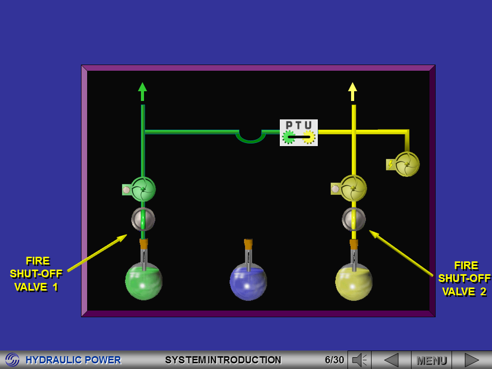
They
isolate the systems in case of an engine fire.

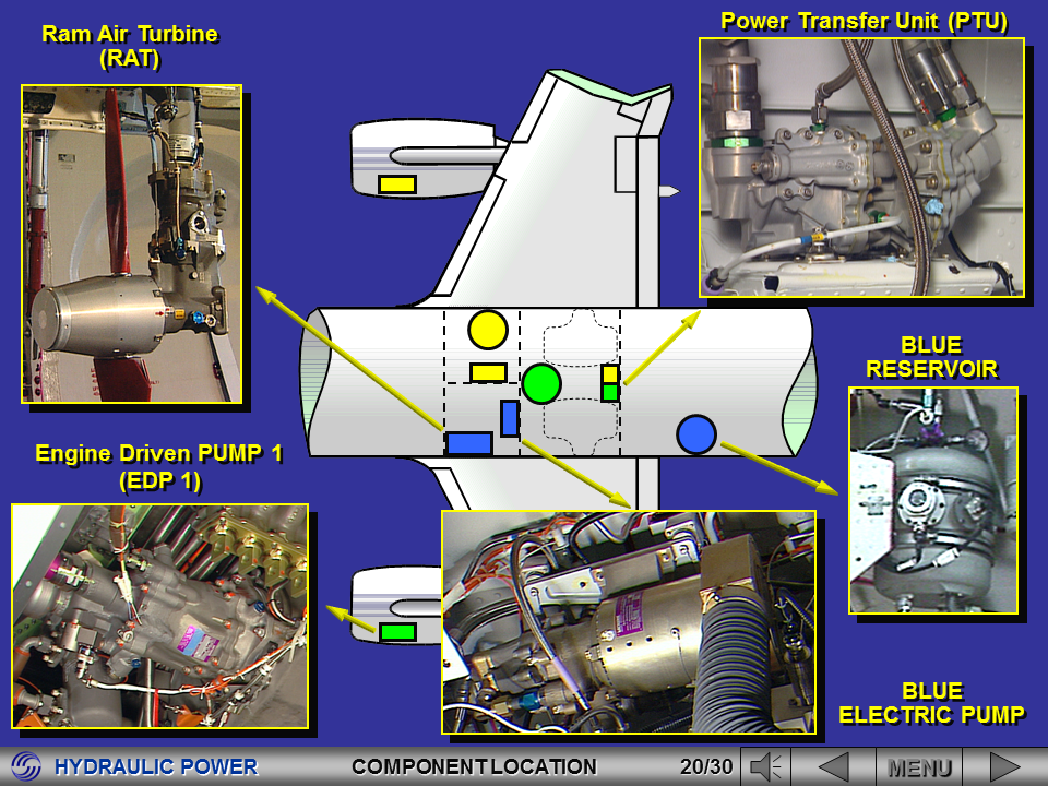
The
electric pump is an hydraulic system main pump.
It
starts running at first engine start up.
Blue
and yellow pumps are fully interchangeable.

The
Ram Air Turbine is deployed automatically or manually. It pressurizes the blue
hyd. system at 2500 psi. It can be retracted on ground only, following a
specific maintenance procedure.


- the reservoirs,
- the fire shut-off valves,
...
- the fire shut-off valves,
...

- the
RAT,
...
...

- the
pressure indications.


Let’s
now go to the ECAM HYD page together with the hydraulic control panel.


Two
deploy solenoids are available to extend the RAT.
The
hot battery bus supplies 28 VDC to the deploy solenoid 1 and battery No2 supplies 28 VDC to the deploy solenoid
2.

On
ground, the RAT retraction is controlled from the RAT control panel located on
the blue servicing panel.
The RAT retraction is electrically controlled and hydraulically operated provided the blue hydraulic system is pressurized.
The RAT retraction is electrically controlled and hydraulically operated provided the blue hydraulic system is pressurized.
RAT INDICATING
On
the RAT control panel there are 3 indicator lights:
- a red light for retraction jack pressurization,
- a green light for RAT stowed,
- an amber light for RAT blades not aligned.
- a red light for retraction jack pressurization,
- a green light for RAT stowed,
- an amber light for RAT blades not aligned.

The
reservoir filling is controlled from the green service panel, by manually
operating the reservoir filling selector to direct the fluid from the external
filling source to the reservoir of the serviced system.
INDICATING
On
the green servicing control panel, the multiple reservoir quantity indicator
allows the selected reservoir to be monitored.


The
MCDU is used for trouble shooting the monitored components through AFS, F/CTL,
INST and L/G systems.
The
leak measurement valve P/B’s are used on ground for maintenance operations
(leak measurement test).

Make sure that the ground
safety-locks and warning notices are in position.
Make sure that the hydraulic system
in maintenance is isolated before you pressurize the other hydraulic systems.
Make sure that the travel ranges of
the flight controls are clear. Movement of the flight controls can cause injury
to persons and/or damage to the aircraft.
Do not get hydraulic fluid or hot
gas from hydraulic reservoir on your body. Use protective clothing to prevent
risk of poisoning and burns. Use solvents, cleaning agents, sealants and other
special materials in a ventilated area. To prevent inadvertent breathing or
contact with your body, use applicable gloves, eye protection and face mask.

Do not push the RAT MAN ON switch.
The RAT will extend.
Make sure that the RAT travel range is
clear before you extend/retract the RAT.

Great Post on Hydraulics . Thanks for your information.
ReplyDeleteThanks for this. It's a good reviewer.
ReplyDeleteThank u. Easy to understand ✌🏻
ReplyDeleteIts a good reviewer thanks
ReplyDeleteThis comment has been removed by the author.
ReplyDeleteUrgent need Female for egg donation with the sum of $500,000.00,whatsapp +91 9945317569
ReplyDeleteEmail: jainhospitalcare@gmail.com
this is very useful for every aviator
ReplyDeleteNice Post....
ReplyDeleteI'm having very interesting information regarding Solar Pump suppliers in India
Very informative !!
ReplyDeleteHydraulic Pump Repairing Service Provider Delhi
ReplyDeleteHydraulic Pump Repairing in Delhi
Thanks for sharing
ReplyDeleteLooking to avail Hydraulic Power Unit in Singapore? If yes then IE group is the best place for you. just make a call on +65 6261 7938 to get best quotes for Hydraulic Power Unit in Singapore.
jyo094lcwi
ReplyDeletegolden goose outlet
golden goose outlet
golden goose outlet
golden goose outlet
golden goose outlet
supreme outlet
golden goose outlet
golden goose outlet
golden goose outlet
golden goose outlet